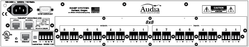
Audia® hardware is represented by three different chassis models: standard Audia; AudiaSOLO; and AudiaFLEX. Standard Audia is a 2RU CobraNet® only chassis and AudiaSOLO is a 1RU non-CobraNet only chassis. These two chassis are available in three I/O configurations: 8-in & 8-out (8x8); 12-in & 4-out (12x4); 4-in & 12-out (4x12). AudiaFLEX is the newest chassis design, which allows up to 24 inputs/outputs, in any combination of channel pairs (see Input/Output below for physical location). AudiaFLEX is available with or without CobraNet. Inputs & outputs are analog, with internal 24-bit A/D & D/A converters, operating at a sample rate of 48kHz. All internal processing is digital (DSP). CobraNet 8-channel Input & Output Expanders are also available.
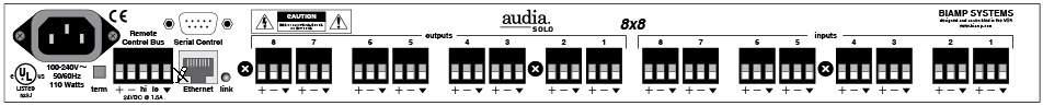
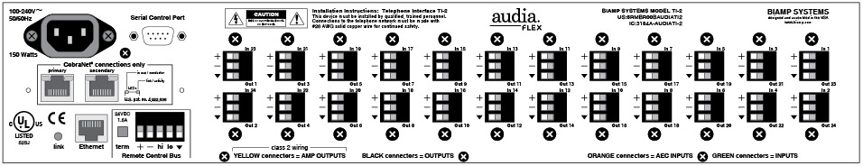
Inputs & Outputs: Inputs & outputs are provided on balanced plug-in barrier-strip connectors. For unbalanced input, wire high to (+) and ground to both (![]() ) & (-). For unbalanced output, wire high to (+) and ground to (
) & (-). For unbalanced output, wire high to (+) and ground to (![]() ), leaving (-) un-connected. With Audia and AudiaSOLO, inputs can be individually programmed to accept either microphone or line level signals. A 12x4 configuration allows Inputs 11 & 12 to be set for stereo input summing. Outputs normally provide line level signal only. However, a 4x12 configuration allows Outputs 1~4 to be set for microphone level. AudiaFLEX inputs and outputs can be individually selected for microphone or line level operation. Besides standard 2-channel mic/line cards for input (IP-2) and output (OP-2e), AudiaFLEX hardware can use special Acoustic Echo Cancellation (AEC-2HD), Telephone Interface (TI-2), and Power Amp (PA-2) cards. NOTE: TI-2 connections to a telephone network must be made by qualified personnel, using #26 AWG solid copper wire for continued safety (T = tip; R = ring). PA-2 speaker connections use the (+) & (-) terminals on individual channels, or the (+) terminal on each channel of a mono-bridged channel pair. The physical location of I/O cards in AudiaFLEX is always as follows: Inputs starting from right (IP-2, AEC-2HD, TI-2); Outputs starting from left (PA-2, OP-2e).
), leaving (-) un-connected. With Audia and AudiaSOLO, inputs can be individually programmed to accept either microphone or line level signals. A 12x4 configuration allows Inputs 11 & 12 to be set for stereo input summing. Outputs normally provide line level signal only. However, a 4x12 configuration allows Outputs 1~4 to be set for microphone level. AudiaFLEX inputs and outputs can be individually selected for microphone or line level operation. Besides standard 2-channel mic/line cards for input (IP-2) and output (OP-2e), AudiaFLEX hardware can use special Acoustic Echo Cancellation (AEC-2HD), Telephone Interface (TI-2), and Power Amp (PA-2) cards. NOTE: TI-2 connections to a telephone network must be made by qualified personnel, using #26 AWG solid copper wire for continued safety (T = tip; R = ring). PA-2 speaker connections use the (+) & (-) terminals on individual channels, or the (+) terminal on each channel of a mono-bridged channel pair. The physical location of I/O cards in AudiaFLEX is always as follows: Inputs starting from right (IP-2, AEC-2HD, TI-2); Outputs starting from left (PA-2, OP-2e).
Ethernet: All Audia units use Ethernet, both for system programming & control. Programming is accomplished using the Audia software provided with each unit. Audia software is for PC computers, with Windows® XP Professional/Vista operating system required. The PC computer must have a network card installed, which supports 10/100BaseT Ethernet. A 10/100Base-T Ethernet switch (not hub) is required when networking multiple units (see System Network Considerations). Ethernet utilizes standard CAT-5 cabling, which has a specified maximum length of 100 meters. However, Ethernet switches which provide fiber-optic interface can be used to extend the physical distance between units within a network.
Remote Control Bus: The Remote Control Bus provides the connection for Volume 8, Select 8, Volume/Select 8, Voltage Control Box, and Logic Box external control devices. (See Remote Control Bus for more information).
CobraNet: Audia configurations are available without CobraNet (for stand-alone applications) or with CobraNet (for networking applications). Individual or multiple 'non-CobraNet' units can be used within a system, but without the ability to share digital audio or DSP resources. However, Audia units with CobraNet can automatically share digital audio & DSP resources within a system, allowing seamless networking. The Audia CobraNet interface supports 64 channels of digital audio (32-in & 32-out), over Fast Ethernet, and is compatible with other CobraNet compliant devices. Therefore, Audia can also be networked with CobraNet products from other manufacturers, expanding the system configuration capabilities. A 10/100Base-T Ethernet switch (not hub) is required when networking multiple units (see System Network Considerations). CobraNet utilizes standard CAT-5 cabling, which has a specified maximum length of 100 meters. However, additional Ethernet switches, or switches which provide fiber-optic interface, can be used to extend the physical distance between units within a network. The primary and secondary CobraNet ports are redundant.
Serial Control Port: After initial programming & configuration, Audia systems may be controlled by RS-232 or Telnet communication from third-party control systems such as AMX® or Crestron®, using the Serial Control Port. Also, external devices may be controlled via the Serial Control Port, by utilizing Command String blocks within the Audia system design
Power Entrance: The Power Entrance provides for connection of the appropriate power cord (included with unit). An internal universal switching power supply accepts 100~240VAC @ 50/60Hz, with a maximum power consumption of 115 Watts.