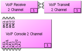
VoIP (Voice over Internet Protocol) Interface blocks provide connection and control via standard Ethernet lines to SIP-based IP telephone systems, and are available only as part of AudiaFLEX hardware. A VoIP Interface consists of three separate blocks as placed through the Object Toolbar; two blocks represent the audio Receive and Transmit functions and a Console block is used to set up and configure the VoIP Interface. A single VoIP Interface can support up to two independent, simultaneous IP calls, each with its own audio path.
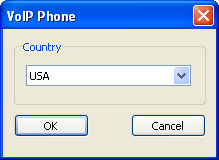
The country is user set when the block is initialized in software. This setting controls what Call Progress Tones are generated and understood. This setting is made per card and governs both lines.
|
|
|
The Receive block provides an output mix of incoming audio and internal ring tone signals for two IP phone lines. Double-clicking the Receive block produces a control dialog box. |
|
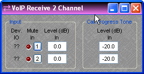
Double-clicking the Receive block produces a control dialog box.
Device IO indicates which hardware input is associated with that software channel. Input provides level adjustment and muting of incoming audio signals. Call Progress Tone Level (dB) provides level adjustment for any internally-generated tones, such as dial tone, busy tone, ring tone, etc.
|
|
The Transmit block provides input connections for outgoing audio signals. |
|
Double-clicking the Transmit block produces a control dialog box with settings for level adjustment and muting of outgoing audio signals. |
|
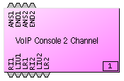
The Console block provides control input nodes for answering and ending calls. ANS1 answers line one and END1 ends the call on line one. Similarly, ANS2 and END2 control line two. Output control nodes provide indication of line status. RI1 indicates that line one is ringing. LIU1 indicates that line one is In Use. LR1 indicates that line one is in a Line Ready state. Similarly, RI2, LIU2 and LR2 provide those indications for line two. |
Double-clicking the Console block produces a control dialog box.
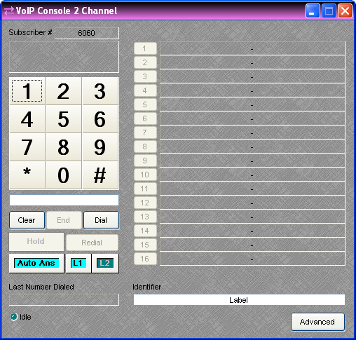
The Status window displays caller ID information when a call is received or error information if the card suffers an error condition during startup. Successful transition to an Idle state indicates that the card has booted, initialized and is ready for use. Keypad (1~#) allows number entry via computer mouse and is active both before the call is initiated and after, which is useful in navigating a voice prompt system or entering an access PIN. A text box below the Keypad displays the number entry and allows number entry via computer keyboard. The number pad on a standard computer keyboard may be used to dial digits provided the Keypad or the text box has focus. Clear deletes the number currently displayed in the text box. End terminates the call. Dial initiates a call with the number displayed in the test box. If no number is present in the text box, the line will simply go “off hook” and wait for a number to be dialed. Hold places the call on hold. Redial initiates a call with the last dialed number. Auto Ans turns the auto answer feature on or off for the currently selected line. (Note: The number of rings before the line is automatically answered is configured in the VoIP Advanced Settings dialog.) L1 selects line one for dialing or configuration. L2 selects line two for dialing or configuration. Last Number Dialed displays the number for the previous outgoing call on the selected line. Idle changes to indicate call progress, while the adjacent LED indicates an active line. Buttons 1~16 initiate speed-dialing. Identifier allows custom labeling for line identification. Advanced produces a control dialog box for advanced configuration editing. Subscriber # displays the Subscriber Number specified in the Advanced Settings Dialog.
|
Right-clicking over buttons 1~16 provides a dialog box for entering speed-dial numbers and labeling. Double-clicking over a previous entry will allow editing.
A Dialer control dialog box can be minimized to create a user control surface (see Customizing Component Objects). |
Clicking on the Advanced button in the VoIP Console Control Dialog will produce the VoIP Advanced Settings Dialog. The Advanced Settings are not available while a call is in progress.
GENERAL
The items on the General Tab of the Advanced Settings Dialog are editable whenever the VoIP line is idle. Call specific settings will be applied to the next call.
Dialing Timeout - This is the amount of time (in seconds) the card will wait after the last dialed digit before sending the call for off hook dialing (default is 3). Dialing the # character will bypass the timeout setting and send the call immediately. This setting is adjustable per line.
Ring Type - This sets the audible ring style for incoming calls (default is Classical) and is adjustable per line.
DTMF On/Off Time - These settings control the duration (in milliseconds) of DTMF tones and the pause time between subsequent tones (default is 50). This setting is adjustable per line.
Enable Out-of-Band DTMF (RFC 2833 Control) - If this setting is enabled and supported by the far end, the VoIP card will send digit presses as a single packet of data to the far end. If this is disabled (default) the DTMF tone will be generated and transmitted as audio. It is advantageous to use this feature because the far end does not need to decode the DTMF tone from compressed audio. If the far end does not support this feature, it will be discovered during call connection and the VoIP Card will automatically revert back to sending DTMF in-band. This setting is adjustable per line.
Auto Answer Ring Count - If Auto Answer is enabled on the dial pad, this setting specifies the number of rings before the VoIP card answers the call (0 - 5 rings, default is 3). This setting is adjustable per line.
Enable Redial - This setting enables the Redial function for the currently selected line, and is adjustable per line (default is on).
RFC2543-Style Hold - When this setting is enabled, the VoIP card will modify the message sent to the VoIP Proxy when it requests a Hold (default is off). Its use will depend on VoIP Proxy Server support. This setting is adjustable per line.
Enable VAD and VAD Threshold - This setting controls whether Voice Activity Detection (VAD) is used on the line. If enabled, the VoIP card will stop transmitting audio packets to the far end to save network bandwidth when the input to the VoIP Card Transmit drops below the threshold defined in the VAD Threshold parameter. Periodic "keep-alive" packets will be transmitted. Not all proxies and end-points support VAD and may drop the call or otherwise misbehave if it is used. This setting is adjustable per line.
Voice Codec Priorities - When initiating or receiving a call the VoIP card will present this list of supported codecs to the proxy server. Codecs are listed in order of priority, from top to bottom, and may be reordered by using the Up and Down buttons. Using this priority list, the VoIP card will negotiate a choice of codec with the other endpoint at the start of each call. The codec can be selected and deselected using the check boxes. If a codec is deselected, it will not be used when negotiating the call. This setting is adjustable per line.
Min / Max Jitter Buffer - Each codec has a minimum and maximum jitter buffer (in milliseconds). Increasing the buffer sizes may improve call quality at the expense of additional delay. Decreasing the buffer sizes may improve delay at the expense of call quality. These settings are adjustable per codec, per line.
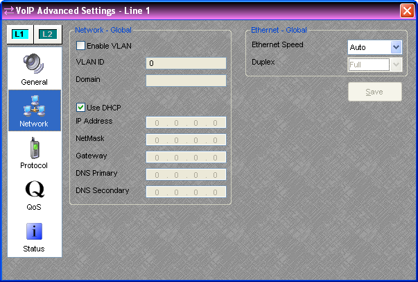
The items on the Network tab of the Advanced Settings Dialog are only editable when Audia Software is not connected to a system.
Enable VLAN and VLAN ID - When this setting is enabled, the VoIP card will tag outgoing packets with the specified VLAN ID and will only respond to packets tagged with the same VLAN ID. VLANs can also be set up by switch port. This should only be enabled if requested by the network administrator. These settings are adjustable per card.
Domain - This setting specifies the search domain for DNS names. For example, if the domain is set to "example.com" and the proxy is set to "voip", the result would be "voip.example.com". This setting is only enabled when DHCP is not being used; otherwise the DHCP server should provide the domain. This setting is adjustable per card.
DHCP / IP Address - If DHCP is selected, the DHCP server should provide the IP Address, NetMask, Gateway, and Primary DNS. It may also provide the Secondary DNS, Domain, and Proxy Address. These settings are adjustable per card.
Ethernet Speed / Duplex - The Ethernet Speed should be left as "Auto" when working with most modern network equipment. If required, the speed may be fixed at 10 or 100 Mbps. When the speed is fixed the duplex must be specified as "Full" or "Half". This setting is adjustable per card.
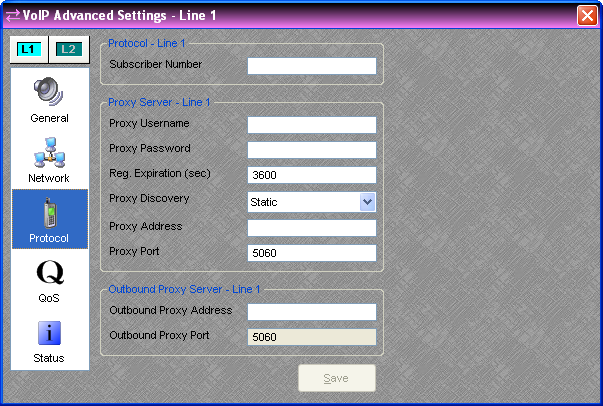
The items on the Protocol tab of the Advanced Settings Dialog are only editable when Audia Software is not connected to a system.
Subscriber Number - This is the number or extension that others call to reach you. It should be provided by the network administrator. 10 characters max. This setting is adjustable per line.
Proxy Username and Password - These are the authentication credentials for the VoIP Proxy Server. They should be provided by the network administrator. 19 characters max. This setting is adjustable per line.
Reg. Expiration - This is how long (in seconds) the VoIP card would like the registration to be valid. The Proxy Server may override this request and requests less than the minimum expiration time in the proxy server will result in an "expiration too short" error. Unless specified by the network administrator, leave the default value of 3600. This setting is adjustable per line.
Proxy Discovery - This specifies the discovery method used to determine the location of the proxy server on the network. "Static" uses the specified dotted quad IP address (e.g. 111.222.333.444) or DNS Name (e.g. "voip.example.com"). "NAPTR" specifies the server with a NAPTR style DNS name. This setting is adjustable per line.
Proxy Address - If "Static" or "NAPTR" is selected as the discovery method, enter the address of the proxy server here. This should be provided by the network administrator. 47 characters max. This setting is adjustable per line.
Proxy Port – This value should be provided by the network administrator (default is 5060). Values in the range of 0 to 65535 are possible. This setting is adjustable per line.
Outbound Proxy Address - Enter the outbound proxy address here. It should be provided by the network administrator. 47 characters max. This setting is adjustable per line.
Outbound Proxy Port – This value should be provided by the network administrator (default is 5060). Values in the range of 0 to 65535 are possible. This setting is adjustable per line.
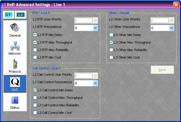
The items on the QoS tab of the Advanced Settings Dialog are only editable when Audia Software is not connected to a system.
QoS is Quality of Service. These settings are used to manage network bandwidth. The default settings are optimized for most VoIP installations; if they need to be modified they should be specified by the network administrator. The VoIP card differentiates between 3 types of traffic and there are two layers of QoS settings available for each type:
RTP - This is the peer-to-peer voice traffic.
Call Control - This is the traffic to and from the SIP proxy server.
Other - All other traffic to and from the VoIP card. DHCP, DNS, ICMP, etc.
L2 User Priority - L2 is Layer 2 in the OSI network model (MAC level). This priority setting is only available on VLAN (802.1Q) tagged packets. This is the 802.1P User Priority (0-7, 7 is the highest priority). The default setting of 6 matches the IEEE recommendation for delay-sensitive voice traffic.
L3 Precedence - L3 is Layer 3 in the OSI network model (IP Level). These flags are available on all traffic and are also known as ToS (0 - 7, a higher number is higher precedence).
L3 Min Delay - The sender requests that data packets be forwarded with minimum delay.
L3 Max Throughput - The sender requests that data packets be forwarded with maximum throughput.
L3 Max Reliability - The sender requests that data packets be forwarded with maximum reliability.
L3 Min Cost - The sender requests that data packets be forwarded with minimum monetary cost. The VoIP card does not support Differentiated Services (DiffServ).
This display window provides an overview of many relevant network settings. When disconnected, a message appears in the Network Status window stating: "Unavailable when not connected."
The "Codec Last Used" field will state unknown when a VoIP-2 card is first installed. The field will update with the actual last used codec after a call has been completed.
Note: Configuration of the proxy server may require the MAC address of the VoIP Interface, and this information is displayed as the first line in network status. The proxy server and outbound proxy server lines will display the address of the server that the VoIP line is registered with. If the line has not yet registered, these entries will be blank.